fixing blown ASUS X555LD

Friend of mine was in Russia when power spike took out her laptop.
Laptop ran out of the battery and would not run on the AC power.

She used local (Russian) repair company to get it “fixed” (for exuberant amount of money).
Unfortunately the repair company could not get it fixed completely due to lack of components, they only managed to make it only work on AC power (no battery).
They also managed to lose bunch of screws…

I was curious what was “fixed” so I opened it up.
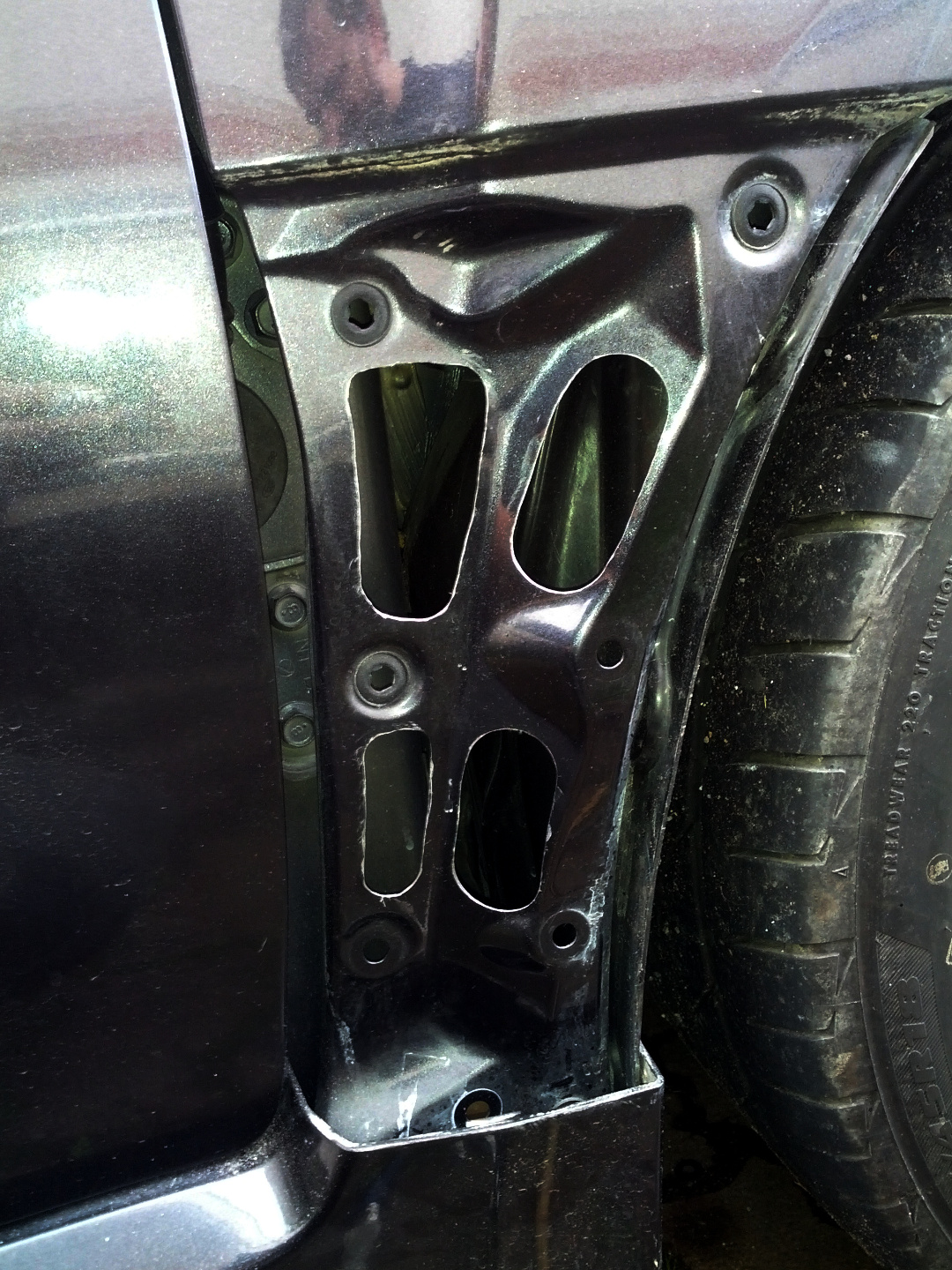
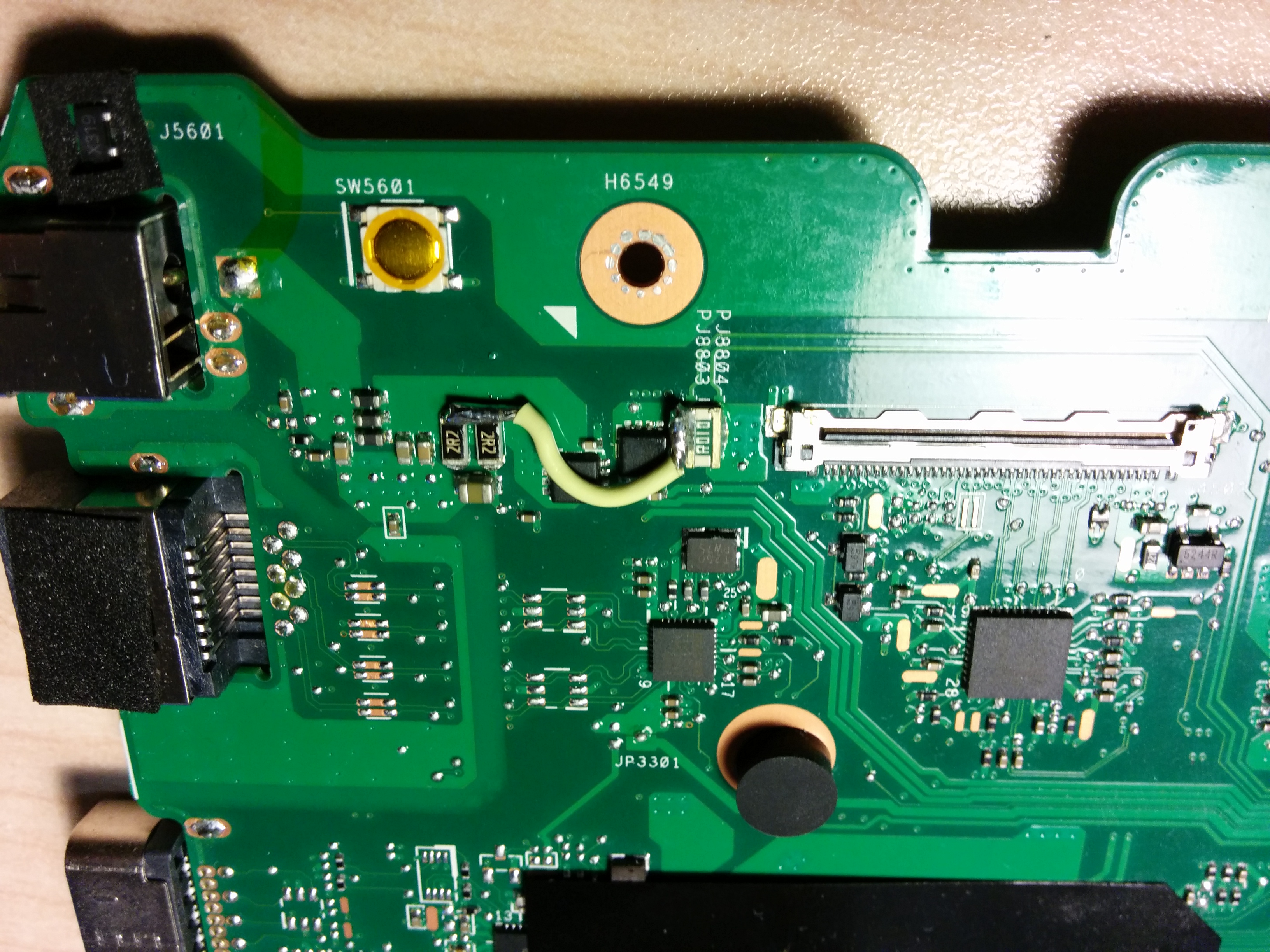
Here is the “fix”:
IMG_20150829_154924

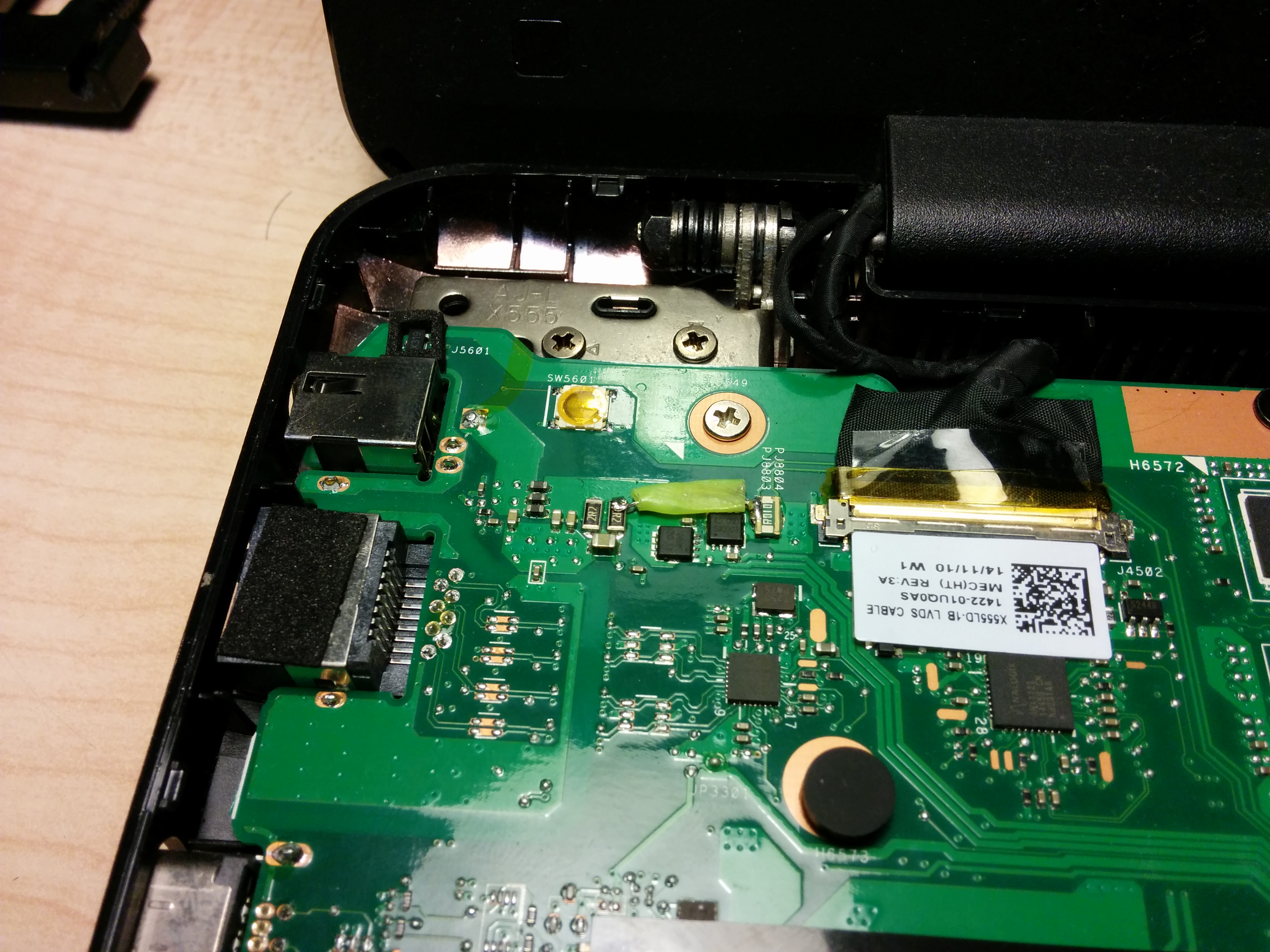
At that time I was not familiar with the laptop circuitry, so I removed the fix and looked up the components underneath.
IMG_20150919_130409

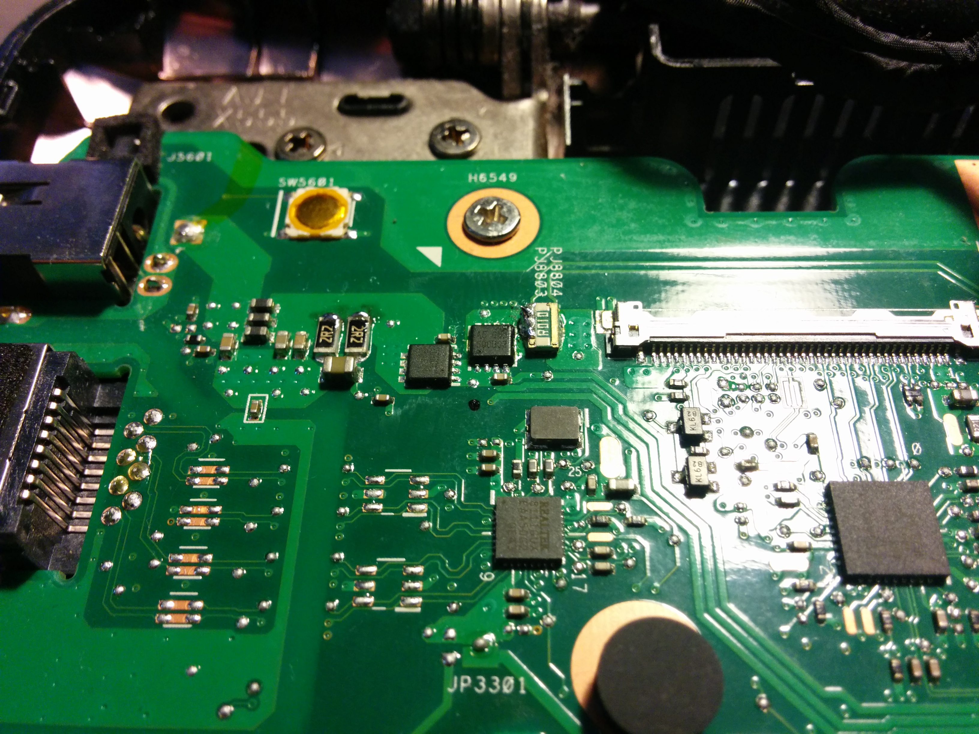
Those little “chips” are labelled as A5GND.
After some googling I found that they are N channel power MOSFETs.

I checked the continuity between drain and source on both of the MOSFETs I found one being completely shorted (blown internal diode?).

Best source of information I could find on them is a thread some obscure Russian notebook repair forum.

Looking on Aliexpress for “A5 GND” results in lots of P2003BEA hits.
Correlating with the forum post above, I found this data sheet for P2003BEA.

I settled for FDMC8296 as the replacement as it has better rDS and almost double of maximum current while being available through eBay (for about $10).

I was curious what was the purpose of these two MOSFETs, so after convoluted searches, I stumbled upon this document: BQ24735
Simply put those two MOSFETs are power source selector switches (AC, BATT, or both).

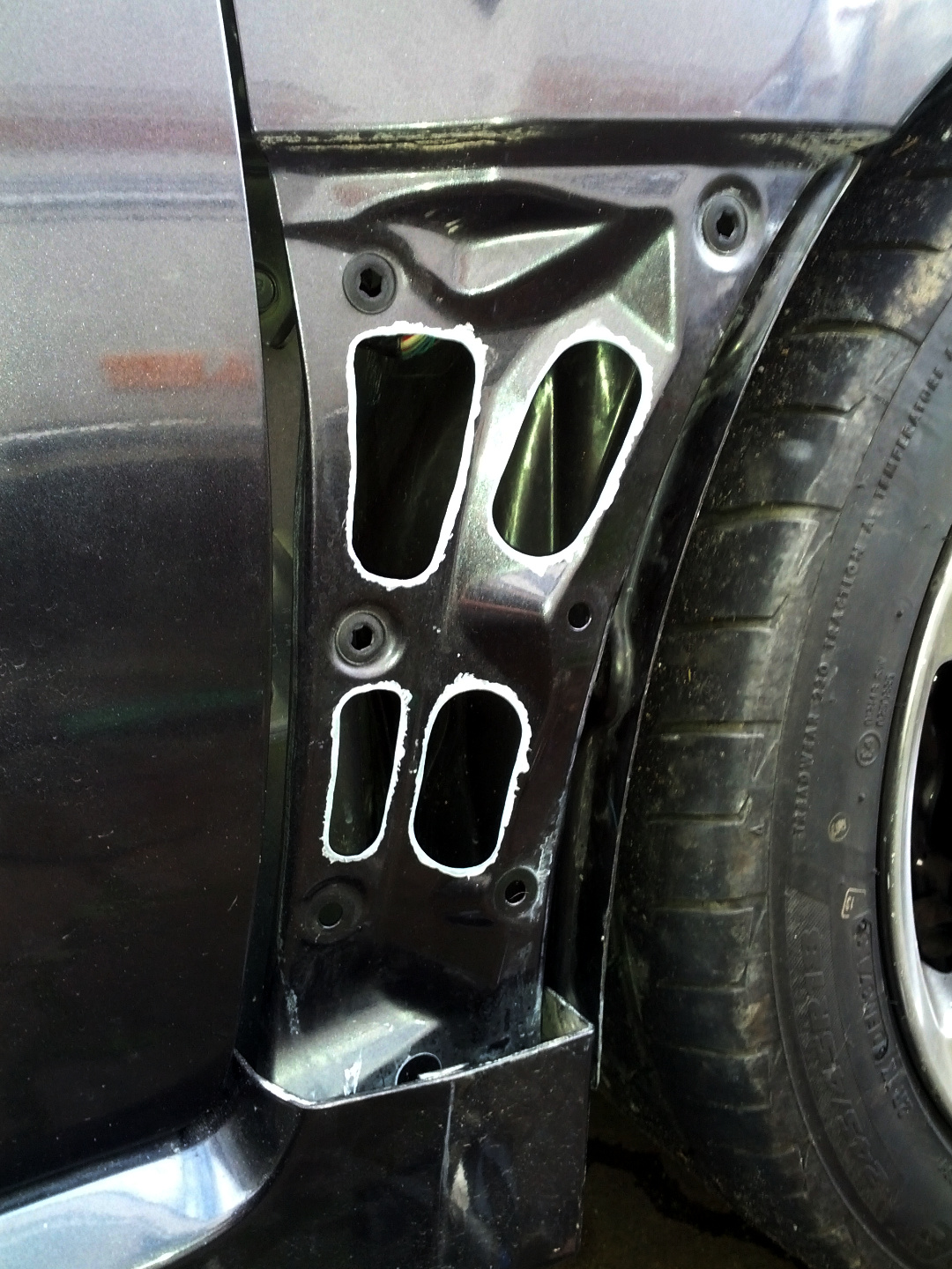
To fix the fix (temporarily) I replaced the dodgy wire bridge with more solid bridge (while I was waiting for hot air gun and transistors to arrive):
IMG_20150829_165318

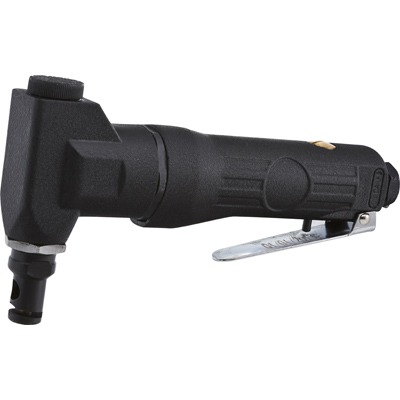
I bought a cheap ($55NZD) air gun on ebay, as I am not planning to do these fixes very often, model: GONGJUE 8018LCD.
8018LCD

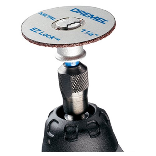
After 3 weeks I received both items: 5x FDMC8296 and a heat gun.

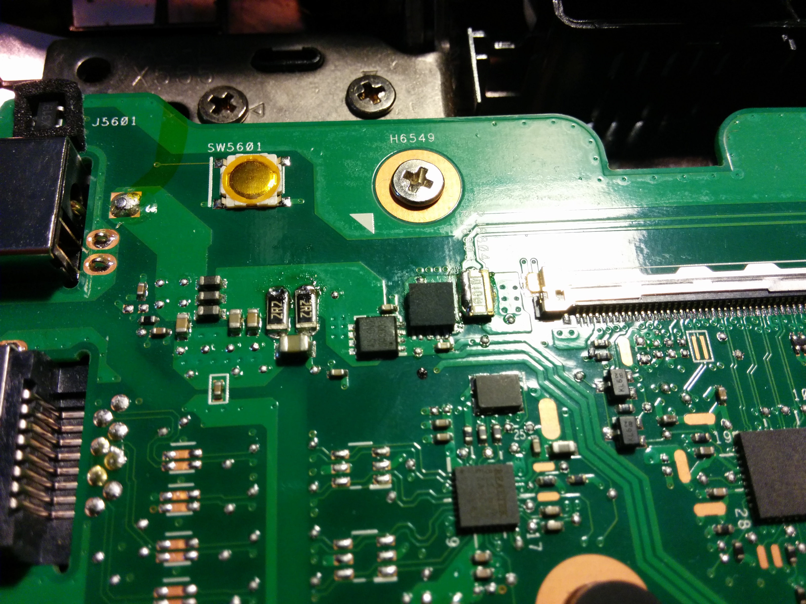
Here is the temporary fix removed and the MOSFET de-soldered:
IMG_20150919_131939

After removal, I made a solder blob on top of the pad and contacts (to dilute original solder and create new “balls”). The excess was removed with a suction gun.

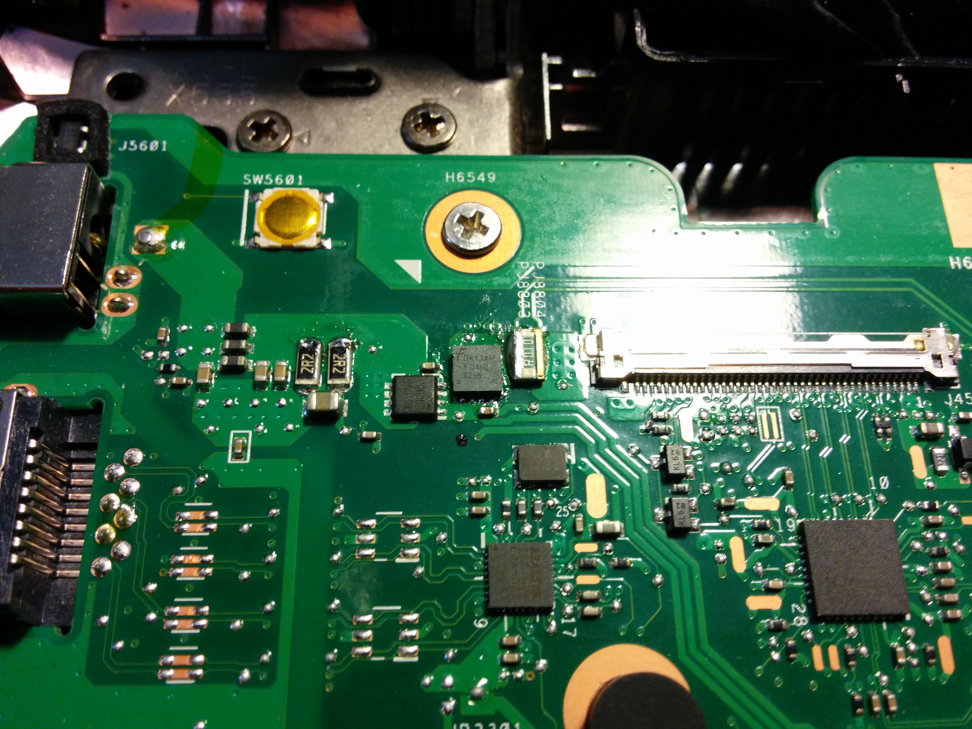
Here is new MOSFET placed (not soldered yet):
IMG_20150919_132301

And here it is soldered:
IMG_20150919_134127

The hot air gun (aka heat gun) was a bit pain in the ass to use: the temperature setting is useless, the smallest attachment is also useless. So I set it to “half” heat, and “3/4” air flow with second smallest attachment, which did the job. The trick was to hold the transistor in place with a screwdriver so it is not blown away. It takes about 10-20 seconds for it to be soldered.

After quick continuity and diode checking I powered up laptop to find it charging the batter. After an hour or so the laptop was operating normally.

On side note I would probably never buy ASUS laptops, as the build quality is shocking.

P.S. for OCD types, yes I cleaned up the resistors that were used for the bridge.

Rescan for new disks in Linux virtual machines

When new disk is added to the Linux virtual machine, sometimes the machine does not detect it.

If you know which SCSI host the disk is added simply issue this command:
echo "- - -" > /sys/class/scsi_host/hostX/scan

Replace ‘hostX’ with appropriate host.

If unsure which SCSI host then quick and dirty way is simply scan all of them:

for host in /sys/class/scsi_host/*; do echo "- - -" > $host/scan; done

To rescan for disk size change do following:

echo 1 > /sys/block/sdX/device/rescan

Where ‘sdX’ is the disk that has been resized.

Toyota CVT oil change

Changing transmission oil should be a simple process, but in case of Toyota CVT (2004 Toyota Vitz RS in this particular case) it is not very simple.

Yes, the drain plug is not really a drain plug.
Yes, the sump has to come out, and new gasket is needed.*

* Except I believe there is another way (quick and lazy) as the oil can be sucked out via the filler plug given the tube is rigid enough. I haven’t tried this method. It is lazy because you don’t inspect and clean the magnets, and you cannot tell the condition of the transmission beyond the oil condition.

Here you will find how I changed it (not necessarily 100% “by the book”, just applied common sense with some googling).

What is needed:

  • Jack
  • Axle stands
  • Oil tray
  • Funnel
  • ~12mm diameter, ~1m long hose (to attach to said funnel)
  • 6mm hex socket (for sump plug)
  • 10mm socket (for sump and filler plug)
  • New sump gasket (p/n 39168-52040 for Vitz RS)
  • Toyota Genuine CVT Oil (p/n 08886-02105 for Vitz RS)
  • New sump plug washer

Toyota would not tell me how much oil is a normal fill. Basically I was told to put the same amount that came out. To figure out correct volume I drained old oil into an empty container and weighted it. Then I emptied old oil out and matched the weight (in same container +100g for spillage) with new oil. Basically I had about 2.8kg of oil (excluding 275g container weight) in the sump (about 3.2-3.5L depending on the temperature and spillage). It works out that oil must be just below the filler hole that I used.

To drain the oil one needs to remove the sump “plug” (6mm hex).
IMG_20150725_182552

It is not a real drain plug as only about 200ml-300ml would come out. Once the fluid stops draining, use the same 6mm hex socket in the hole where the sump plug was, and gently unscrew the plastic tube. This time there will be about 1-1.5L of fluid coming out.

Here is the plastic tube that sits inside of the drain hole:
IMG_20150725_182709

By removing the plastic tube the oil level will become just below the gasket line, if the car is jacked up front up the fluid will be above the gasket line (about 200-300ml) on the far side of the sump (due to angle of the car). The spill can be avoided if the rear of the car is jacked up as well to make it levelled. I found this hard way.

Once it is drained via sump plug, put the plug back in and unscrew 10mm bolts holding the sump. You will find the sump is “stuck” and will need a gentle pry to remove it. Watch out for oil as there is about 1L of oil left in the sump!

IMG_20150725_183302

Clean magnets while the sump is out (they should have minimal amount of shavings):
IMG_20150725_183930

New gasket:
IMG_20150725_184201

Make sure the mating surface is clean:
IMG_20150725_184413

Don’t forget to screw in the plastic tube! It goes in the same way it came out.
Check the condition of the strainer (should be clean).

The torque that the sump screws needed to be tighten to is very tiny (8-10Nm), I don’t have exact figure, but it should not be too different from other Toyota auto transmissions (hence the 8-10Nm figure), it must be done evenly. Do not over tighten, as the torque required is almost finger tight! I tightened it in multiple passes (allowing gasket to spread evenly). Best way to start once the sump is held by all screws, is to undo all screws so there is a play (sump can be pushed up) and tighten them in criss-cross pattern with very small torque evenly.

Oil comes in a metal tin can:
IMG_20150725_191052

The filler hole (in the centre of the picture, black flat oval plug) is located where the dipstick on normal auto will be, it is blocked by a plug held by a 10mm screw:
IMG_20150725_190136
To find it just look down from throttle body, it will be just below the transmission breather, in midst of various plugs a next to oil cooler.

Here is the filler plug up close:
IMG_20150725_194519

I used a funnel with a plastic hose to fill new oil:
IMG_20150725_194137

Here is another angle of the filler with tube in it:
IMG_20150725_194155

As interesting note to this exercise, one could retrofit dipstick from conventional auto, as well as to weld on a real sump plug, to make these changes easy enough (although they are not frequent enough to warrant such measures).

simple mysql slave

Simple mysql master->slave replication.

Assumptions:
The mysql/firewalls/etc are already setup, there are no writes going on to master during the setup (or there are provisions to take care of master/slave mismatch, like percona toolkit).

On master:
in /etc/mysql/my.cnf uncomment the following lines :

#server-id              = 1
#log_bin                        = /var/log/mysql/mysql-bin.log

And comment the following line:

bind-address            = 127.0.0.1

restart mysql:


service mysql restart

in mysql run following:

GRANT REPLICATION SLAVE ON *.* TO 'repl'@'{IP}' IDENTIFIED BY '{PASSWORD}';
FLUSH PRIVILEGES;
SHOW MASTER STATUS;

Where {IP} is the IP address of the slave and {PASSWORD} is the password of your choosing.
Note: username does not have to be ‘repl’.

The SHOW MASTER STATUS should return the following:

+------------------+----------+---
| File             | Position | 
+------------------+----------+---
| mysql-bin.000001 |      100 |
+------------------+----------+---

Record two this: File and Position (this will be used when setting up the slave).

On slave:
Dump the database(s) in question and import it into new slave, eg (for each database):

mysql -e "CREATE DATABSE {DB}"
mysqldump -h{MASTER_IP} -u{MASTER_USER} -p{MASTER_PASSWORD} {DB} | mysql {DB}

assuming the root user has no password locally on slave.

Uncomment and modify the following lines (make sure server-id is unique):

server-id              = 2
log_bin                        = /var/log/mysql/mysql-bin.log

And comment the following line (needed only if you need to access slaves remotely):

bind-address            = 127.0.0.1

restart mysql:

service mysql restart

In mysql, setup replication:

CHANGE MASTER TO MASTER_HOST='{MASTER_IP}',MASTER_USER='repl',MASTER_PASSWORD='{PASSWORD}', MASTER_LOG_FILE='{FILE_FROM_MASTER_STATUS}', MASTER_LOG_POS={POSITION_FROM_MASTER_STATUS};
START SLAVE;

Note: MASTER_LOG_POS is unquoted integer.

Check if replication is running:

SHOW SLAVE STATUS \G

NZ Police Speed Enforcement documents

A while ago (mid December 2014), I made an Official Information Act request to NZ Police regarding specs and other information of their speed measuring/enforcement equipment.

The reason behind such request was because I thought no speed limit tolerance (or 1km/h ?) was absurd, and bluntly put very stupid.

Here are the documents that I received:
1) Response letter with some answers to my questions (included in the letter in italic).
2) Speed_Detection_Equipment_Operators_Manual.
3) Stalker_Lidar_EU_Operators_Manual

Here is the equipment/accuracy table:

Accuracy_table

So basically they are stating that almost all their equipment is +/- 0.6km/h accurate, be that hand held LIDAR or vehicle mounted RADAR equipment.

I find it incredible that it is possible to go from +/- 3.2km/h accuracy (http://www.stalkerradar.com/law_dual.shtml see specifications tab) to 0.6km/h for Stalker Dual RADAR system. Especially considering they use RADAR to get ground speed and speed of the vehicle, which means each reading should have +/- 0.3km/h accuracy!!! But that is my speculation.

I found a few interesting things in the manuals, which opens a few possibilities when contesting unfair reading.

The radars are tested daily with tuning forks(*).

There should be a “Tracking history”.
What that means is that the police officer should identify your vehicle, ie: it cannot get a blind reading from radar! For example if they claim they have a reading while you where behind the corner, they cannot fine you.
They should get a clear Doppler audio feedback (although it will be hard to argue that).
They should have a ground speed estimation from the vehicle speedometer(**) if they are moving.

The LIDAR spread is is about 0.17 degrees, at ~800m (upper end of the working range) the “spot” is about 2.4m circle, at such distance it is possible to get the wrong reading if there are other cars in vicinity (ie partially covered by the laser spot).

Apparently the NZ LIDARs are “immune” to sweep effect (although how does it know the difference between officer tracking the car or officer sweeping the car?). I bet all it does is filters out jitter, but it is possible to sweep without creating jitter.

Interesting thing is that the headlights that emit a lot of infra-red light can interfere with the operation of the LIDAR.

The LIDARs can only be operated stationary.

With LIDARs officers must write down the speed locking distance on the ticket.

The officer must retain the locked values for viewing by the allegedly offending motorist. In addition the remotely operating officer (ie on overpass) should record the vehicle description, speed and distance reading.

All speed measuring devices used by Police to enforce speed limits should have a valid accuracy certificate not older than 12 months.
All police vehicles that are equipped by radar should have a valid speedometer certificate of accuracy not older than 12 months.

Every shift the unit must go through various test which should be recorded in the logbook.

In summary (direct extract from the document):

Documentary evidence

To comply with evidential requirements the operator will need:
* a copy of the speed detection device logbook relating to the day in question.
* a copy of the certificate of accuracy issued within a year of the date of the offence.
* a copy of the certificate of accuracy for the patrol vehicle used in the operation of the radar device or
* a copy of the certificate of accuracy for the patrol vehicle used for the weekly check in the case of a laser device.
* a copy of the operators Certificate of Proficiency for radar and laser devices.

Evidence in court

The operator must be able to give in evidence that:
* they are a certified speed detection equipment operator.
* they conducted the required tests for the unit and found it to be working correctly.
* a tracking history was established for the target vehicle.
* the code of operations was complied with.

There is interesting gotcha that makes 0.6km/h accuracy of the radar units meaningless:

Confirm patrol vehicle speed is consistent with the speed readout on the unit within +/- 3 km/h. This is achieved by travelling at a consistent speed, appropriate to the speed limit being operated in, and checking that the true speed(according to the certificate of accuracy) is the one displayed on the readout. Record the results in the logbook.

As far as I understand the document, what this test does is test that vehicle speedometer is within of +/- 3km/h of the RADAR grounds speed reading. This test never tests that the unit are within the specified accuracy, and might well be off by +/- { whatever is speedometer inaccuracy + 3km/h }.

The same applies to the laser units:

On a weekly basis the laser unit readout needs to be checked using a drive though by a patrol vehicle with a certified speedometer. This is carried out by having the driver of the vehicle drive at a steady speed towards the laser operation area. The speed will be relevant to the area of operation. The driver should flash their headlights or advise using the radio when the vehicle speed is steady and the laser operator will check the speed. The member using the laser will advise the vehicle driver of the results of the speed check, The driver will advise the speed they were travelling at after checking the certificate of accuracy to determine the true speed. Where the margin of error exceeds +/- 3 km/h the unit is to be withdrawn for servicing The results of the check must be recorded in the logbook (vehicle speed/checked speed). for example 64/65; 46/46; 75/75.

Since the daily test are only conducted to ensure that the LIDAR and RADAR units are within 3km/h + speedometer inaccuracy, then one would conclude that at the day the units in question are only good for +/- >3km/h. In reality because of the speedometer inaccuracy used by the police for testing it could be well over 6km/h!

* The tuning forks.. They are definitely temperature dependant devices, I am yet to find an accurate source, my initial research shows worse estimate of 1% change for every 5 degree Celsius or best estimate of ~0.07% change (that wildly differs for the material as well).

** The speedometer accuracy can also vary wildly, depending on tyre wear, temperature/tyre pressure. For example at the beginning of the life the tyre has about 8mm of usable thread.
Assuming the nominal diameter of 205/60/15 Tyre is 627mm at the beginning, after ~60% wear it is 617mm. That is roughly 1.6% change. Which would translate to 1.6% higher reading. At 90% wear it adds up to 2.4%. Combined with under inflation that can go over 5% easy.

Navman (Mio) MiVue 388

Navman_MiVue388

I bought Navman MiVue 388 for holiday in Australia, as I was going to do a few thousands kilometres worth of driving.
This camera is sold everywhere else under Mio brand. It is not a Navman product.
When I was purchasing this dash camera I had few prerequisites (which it met, somewhat):
1) 1080p
2) suction cup mount (for easy removal from rental)
3) Modest size
4) Available next day
5) Reasonably priced (under $250)
6) GPS
So basically the only product in New Zealand that met those was this camera.

Whatever you do, do not buy this dash camera. There is nothing really positive I can write about it (apart that it supports 64GB VFAT formatted card, despite the specifications). It pales in comparison to a much cheaper G1W, or Mini0806 (also crap! DO NOT BUY THESE!) or even my dated Blackvue DR400G-HD II. If you are after a good value for money camera get G1W for ~$60USD. Same applies to MiVue 338/358.

Image quality is very grainy:

I didn’t test the camera with optional CPL filter as Navman didn’t sell it at the time (it could have been sources from eBay as Mio branded).

Beyond image quality there are other major issues:

* Suction cup mount is a standard GPS mount, is way too big and vibration prone. It is not very good and falls off after few hours. Not possible for discreet mounting in a smaller car without major view obstruction.
* After 1 month of operation the face plate (screen cover) fell off. It was stuck on by two short strips of double sided tape. After reattaching second time, I gave up and now the camera is used without it.
* Occasionally it decided to completely lose time settings and gets stuck on Setup Time screen. While in that state it does not record!!!
* Cannot turn off blue pixelated “MiVue388” logo on top of the screen (without hacking firmware).
* Battery life is hopeless (about 1 minute and 30 seconds). Good luck actually using park mode.

Two of the issues were because of the climate in New Zealand; this camera is not suitable for being attached permanently on the windscreen due to heat. It is probably far worse for it in Australia.

To address the shitty mount I have decided to build my own mount (secured by not suction cup but double sided tape).
The materials I used are the following:

* Piece of scrap aluminium plate (some random cut off)
* A random drawer knob that I found at hardware store (a 16mm ball with threaded hole and a screw).
* 3M moulding tape
* Black paint

IMG_20140816_125834
IMG_20140816_125848
IMG_20140816_125901
IMG_20140816_125928

Test fit:
IMG_20140816_130112
IMG_20140816_130157

Painted and assembled:
IMG_20140816_131827
IMG_20140816_131849
IMG_20140816_132327

Finished product:
IMG_20140817_141948
IMG_20140817_142026

With my mount the dash cam no longer blocks the view, in fact it is almost not visible (apart from status LED) from drivers seat. It is also very discreet from outside as it is masked by mirror contour.

Tuning GRB STI for 95 RON

Due to scarcity of 98 Octane (RON) in New Zealand, beyond major centres, I got my WRX STI tuned for 95.
Tuning has been done by David Wallace (tunetechnic.co.nz). I chose David because I had really good experience with him tuning my ST165 Celica GT4 (when he was with torque performance), as well as he has really good reputation.

Thanks to Subaru open ECU interface the process was very painless. The most difficult part of this tuning process is getting fuel tank empty to ensure it has 100% 95RON.

Basically David uploaded new tune at my place (via OBDII connector), and we went for a drive while David was monitoring the sensor output. After some minor adjustments the final tune was uploaded at the end of the drive.

The whole process took a little bit over an hour.

I am very happy with new tune, as not only I can safely fill up with 95 RON (although it is still better to run on 98 RON as ECU will take advantage of that), but it actually performs better.

Highly recommend doing this for every JDM GRB STI in New Zealand (even if it stock like mine).

GRB STI TGV deletion

Q. What is TGV?
A. Tumble Generator Valve.

The purpose of TGV is to create swirl/tumble of air-fuel mixture to improve emissions at certain conditions.
TGV consists of butterfly valves located before the injector in each intake runner. These valves when closed force air through a small passage.

Generally under normal operation these valves are open. The main reasoning of TGV removal is small performance gain due to removal of restrictions from open butterfly valves. As bonus it will also increase reliability by making the system simpler.

One thing I noticed: since removal (even before tune) the “hole” around 3000rpm during warm-up has disappeared.

The TGV system on GRB STI consists of following parts:
Two TGV position sensors.
Two TGV actuators.
Four butterfly valves connected in pairs on each bank.

It is located under manifold, in the spacers between heads and the manifold. The cars equipped with TGV can be recognised by having sensors and actuators attached to the sides of manifold spacers.

Here is the TGV in all of its glory (the black spacer is Zerolift TGV deletion “kit”):
IMG_20140411_214318

The exercise of TGV removal (aka TGV deletion) for me was a “by the way” thing as I was getting my car retuned anyway (I needed to run 95 octane safely as in New Zealand beyond main cities 98 octane is very scarce).

Due to difficulty of locating the genuine spacers without TGV (these exists and normally found on 2004-2007 WRX STI), I settled for plastic Zerolift TGV deletion kit.
A bit of warning on Zerolift TGV deletion kit: because they are plastic THEY MUST BE TIGHTENED TO CORRECT TORQUE! Which is very low, and feel little bit tighter than finger tight. They will crack otherwise!
Once I reach 100,000kms and have cam belt due, I will replace them with genuine spacers.
Another thing is because my STI is JDM the Zerolift kit didn’t fit correctly (the middle holes didn’t line up), I had to modify the manifold to fit (slot the holes):
IMG_20140411_214958

The Zerolift TGV comes with O-rings, and these must be installed evenly (a bit of exercise for fingers). Do not use manifold gaskets!

At the same time I decided to do the spark plugs, I settled for LFR7AIX (one range colder, iridium). Note: unlike previous EJ20, EJ207 (at least on WRX STI) has long reach spark plugs!

Now to the process (it was my first time working on STI)…

Intercooler and battery out:
IMG_20140411_163616
IMG_20140411_163606

Remove BOV:
IMG_20140411_164924

Remove earth lead and fuel lines:
IMG_20140411_164914
IMG_20140411_163611

Remove coolant bottle:
IMG_20140411_163833

Remove air pump hoses:
IMG_20140411_165549

Remove air box:
IMG_20140411_174455

Remove alternator:
IMG_20140411_170202
IMG_20140411_174521

Misc:
IMG_20140411_180037
IMG_20140411_180052
IMG_20140411_180115

The main loom will need to be disconnected from the plug near firewall, and then after unbolting and unclipping numerous hoses the manifold comes straight up (almost):
IMG_20140411_183142
IMG_20140411_204553

More of TGV:
IMG_20140411_205315
IMG_20140411_214222
IMG_20140411_214232
IMG_20140411_214305

Now for the spark plug change.
The access if fairly limited but no need for special tools or jacking or pushing the engine:
IMG_20140411_165642
IMG_20140411_170236

The coil is held by 12mm bolt and comes out with a bit of wiggling.
The coil:
IMG_20140412_094009
IMG_20140412_094001
IMG_20140412_093951

The spark plug:
IMG_20140412_094436
IMG_20140412_094753

Back to the TGV.
Assembled manifold with TGV deletion kit:
IMG_20140412_134457
IMG_20140412_134732
IMG_20140412_134736
IMG_20140412_134743

Make sure the PCV valve is connected back (easy to forget as it is right under the throttle body):
IMG_20140412_135348
IMG_20140412_135422

All together (bar alternator):
IMG_20140412_175503

Since spacers are plastic I decided to add an earthing wire. I have also moved original earthing wire to the head (just on top of the AVS solenoid). I had to drill a hole on the A/C pump bracket and cut thread as I found no suitable place for the new earth wire:
IMG_20140413_100420
IMG_20140413_100448
IMG_20140413_100842
IMG_20140413_100853

Starting the car without TGV brought up numerous non-TGV related error codes. To test that they are false positives I have connected the original spacers back:
IMG_20140414_170155
It turns out that they definitely were false positives. Interesting that ECU would only trigger TGV error codes if TGV was partially missing.

To get it ready for new tune I had to drain the fuel tank. The reason for draining as it was filled up with 98 RON, and I needed for tune to be safe for 95 RON. Unfortunately I found the hard way that you cannot simply remove the return line and run the car until it stops, due to shape of the tank. It would only empty the fuel pump side this way (there is a siphon between sections which is feed by return line).
To drain the tank completely I had to remove fuel pump and the cover on other side. Then I had to siphon both sides (very difficult on such low car), as GRB is missing drain plug on the fuel tank.
Here is what fuel pump (housing) looks like:
IMG_20140415_195750
IMG_20140415_195827

Enabling side vents on GRB WRX STI

The GRB WRX STI comes with side vents from factory.
STI-sidevent-00

Unfortunately they are not functional and there only for aesthetics, as you can see on this pic:
STI-sidevent-01
The vent cover is plastic, held in place by clips. It can be pulled of with minimal disassembly by unscrewing/unclipping inner guard on the bottom, and unclipping the side skirt in the vent area.

I used three power tools to expand and create holes:
1) Air powered nibbler (bought it from supercheap):
Nibbler
2) Dremel with metal cut-off disk:
Dremel
3) 13mm drill bit (for starting point for nibbler).

All of these could be done with just dremel, but making it clean would be difficult.

Here it is cut out and cleaned up:
STI-sidevent-02

Primed:
STI-sidevent-03

Painted:
STI-sidevent-04

Not pictured: inner side of plastic vent cover has a rubber flap, I removed it as well.

Assembled:
STI-sidevent-05

In the end I am happy with this little mod, even by having radiator fan on on stationary car is enough to feel warm air coming from the vent.

Converting Blackvue Dashcam gps log

It appears that Blackvue dashcams log GPS data in “almost” NMEA format.
It is possible to convert the file using gpsbabel utility into KML format that google maps/earth can understand.
All you need to do is strip time stamp appended to each line in the log and them process the output with gpsbabel:

cat {BLACKVUE_GPS_LOG}.gps | awk -F ']' '{ print $2 }' | egrep -v '^$' > {BLACKVUE_GPS_LOG}.nmea
gpsbabel -i NMEA -f  {BLACKVUE_GPS_LOG}.nmea -o KML -F {BLACKVUE_GPS_LOG}.kml

This is what log looks like:

[1389266060242]$GPRMC,221417.990,A,4533.1826,S,16737.5506,E,054.7,035.5,080114,,,A*77

[1389266060242]$GPVTG,035.5,T,,M,054.7,N,101.4,K,A*0C

[1389266060242]$GPGGA,221418.990,4533.1701,S,16737.5631,E,1,11,1.1,204.6,M,1.7,M,,0000*78

[1389266060242]$GPGSA,A,3,16,07,03,19,23,13,10,06,09,27,08,,2.0,1.1,1.7*3D

[1389266060242]$GPGSV,3,1,12,13,80,310,39,07,50,247,36,23,50,019,48,03,48,066,46*71

[1389266060242]$GPGSV,3,2,12,16,45,128,43,27,42,084,44,06,41,096,44,19,28,038,46*79

[1389266060242]$GPGSV,3,3,12,10,26,260,31,08,19,261,32,09,16,257,26,05,06,210,*77

[1389266061239]$GPRMC,221418.990,A,4533.1701,S,16737.5631,E,054.8,035.0,080114,,,A*7F