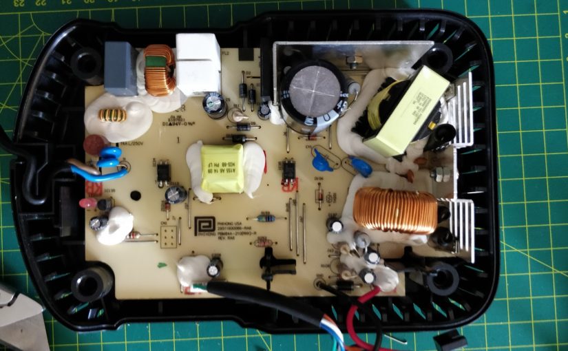
Here is how I converted north American Dewalt DCB101 to proper supply voltage (warning: do it at your own risk).
I have made this conversion based on many internet forum posts and youtube videos.
Note: there are at least two versions of this charger and newer version requires rewinding the transformer (at least according to internet).
Why? For some stupid reason 240V chargers locally cost 2 to 3 times more than in USA.
Parts used:
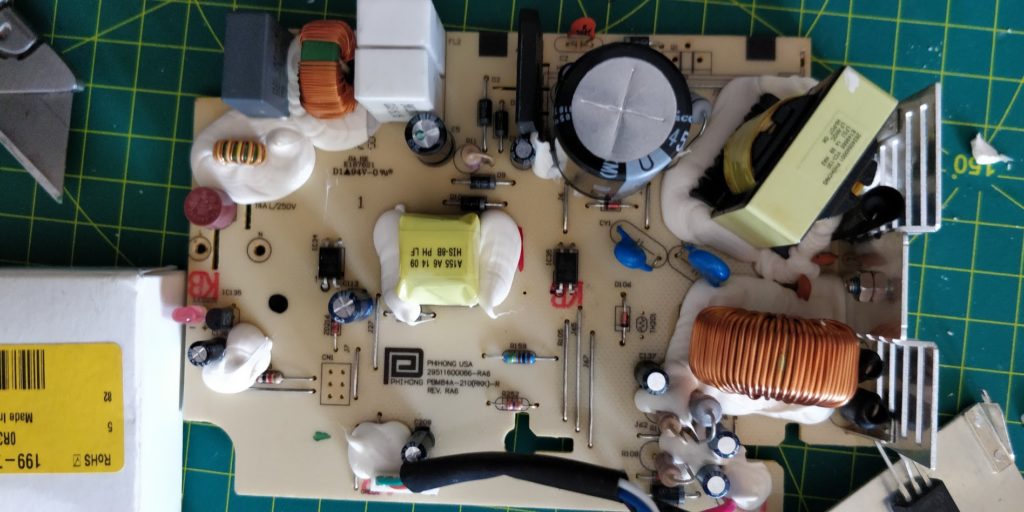
1x 450v 100uF 105’C Capacior
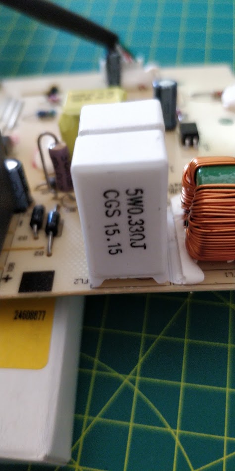
2x 0.33 5W inrush limiting resistors
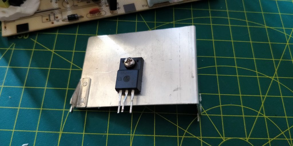
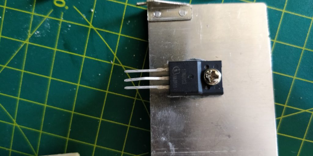
1x SPA17N80C3XKSA1 N-Channel MOSFET,
2x* 07D471K MOVs (whatever I had)
1x Figure 8 to AS/NZS 3112 sacrificial cable
* this part is optional, can use 1 MOV if physically large enough.
NOTE: I chose wrongly sized capacitor (10mm pitch, 22mm dia, 40mm tall), correct size is:
8mm pitch
18mm diameter
36mm tall
must be 105’C, low ESR, 450V, ~100uF (capacitance is not that crucial).
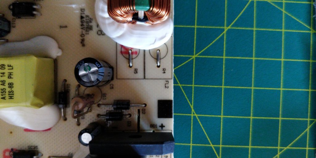
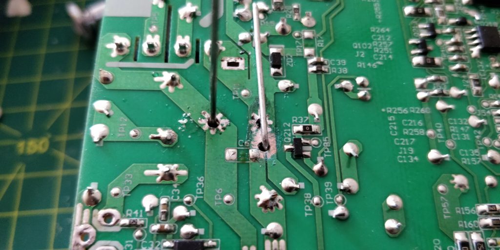
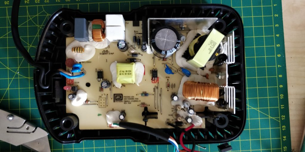
The resistors replace links labelled as R4 and R5:
It was much easier to desolder the heatsink and the transistor first before getting to the capacitor:
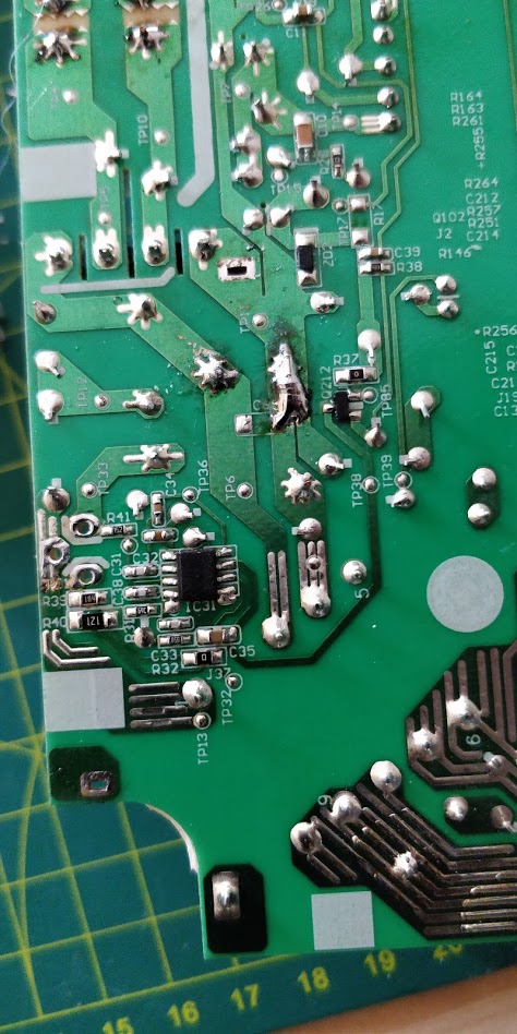
Because I had wrong capacitor I had to butcher the board:
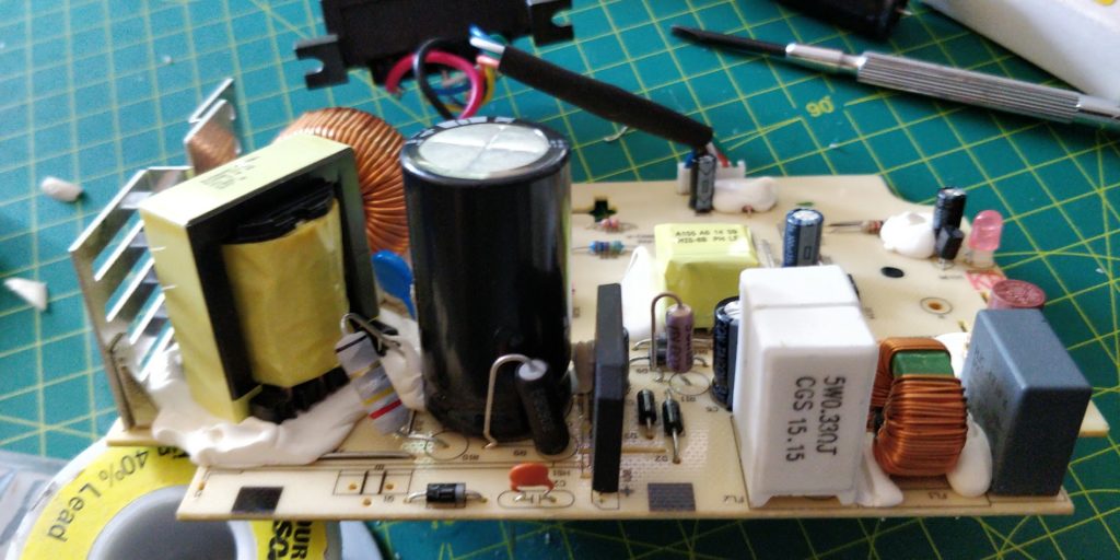
New transistor:
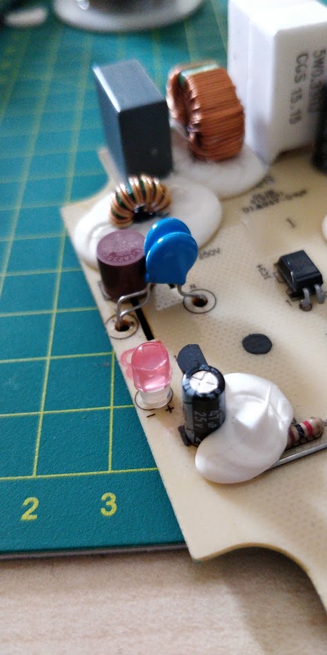
MOVs fitted (not the best positioning but didn’t want to put them under due to proximity to plastic case):
Testing in the “Explosion Containment Tub”:
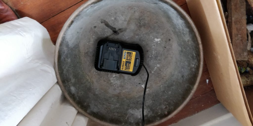
Since I didn’t had a DeWalt battery handy I will report back later if it is actually working…
P.S. yes with 40mm capacitor it is possible to assemble the case, and no, it is not perfect and rather tight, the PCB is bowed and the gap between case halves is uneven. The capacitor is the most expensive part so choose wisely.