For a while I was looking a simple camera that I could use with micropython and ESP32 board.
Initially I looked at Arducam 2MP camera, but that turned out to be a real pain to interface with, and it took up way to many IO pins for my liking. The micropython is barely fast enough to actually do handle the packets. Of course there weren’t off the shelf library to do what I wanted. In addition the image quality was not great, even though it was a 2MP camera.
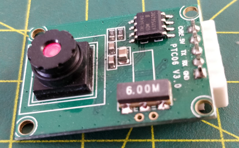
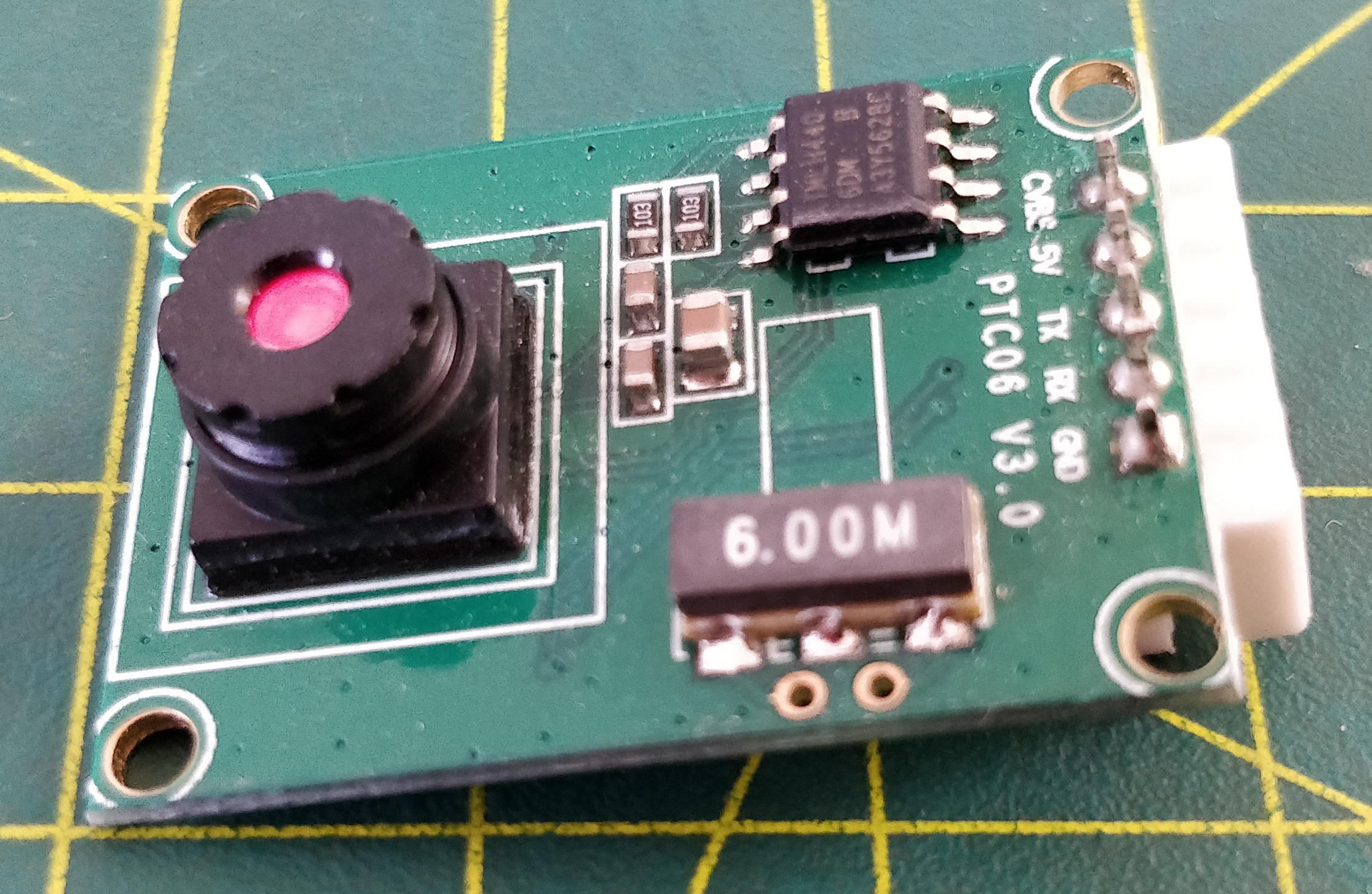
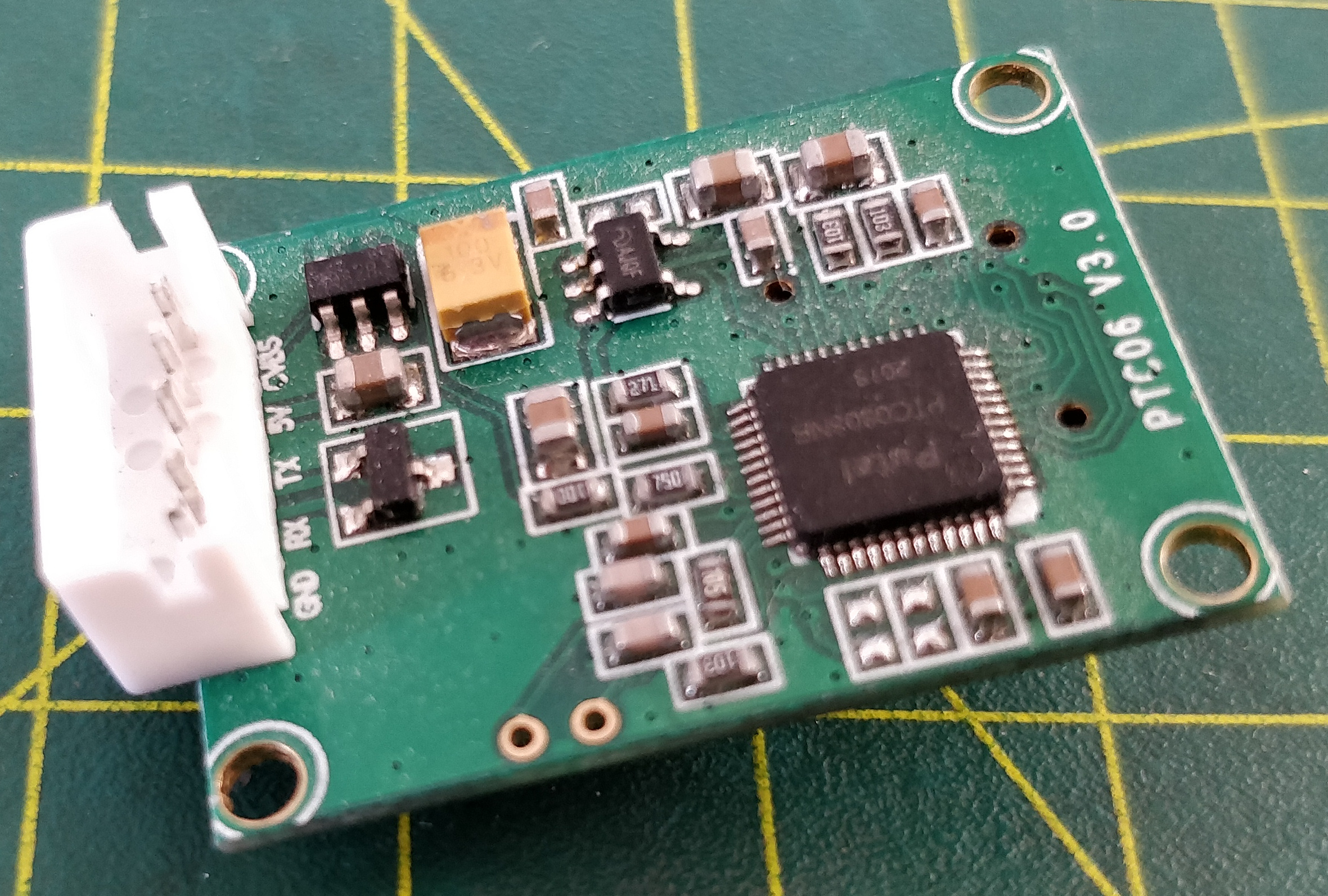
I decided to try a low cost UART (serial) camera instead. Downside is the camera only 640×480, the upside is that the power consumption is around 30mA (half of what the Arducam is). Another upside that the camera is physically smaller (specifically the lens). Most importantly the UART protocol the camera uses is very simple, and it only needs two IO pins to operate.
Here is the mycropython code:
from machine import UART
"""
PTC06 Camera interface
Copyright GPL3.0 sergei.nz.
https://www.mouser.com/datasheet/2/737/adafruit_english%20camera-1217461.pdf
"""

RESET = b'\x56\x00\x26\x00'
START_CAPTURE = b'\x56\x00\x36\x01\x00'
GET_IMGSIZE = b'\x56\x00\x34\x01\x00'
GET_FRAME_START = b'\x56\x00\x32\x0C\x00\x0A'
GET_FRAME_END = b'\x00\x0A'
STOP_CAPTURE = b'\x56\x00\x36\x01\x03'
GET_RESOLUTION = b'\x56\x00\x30\x04\x04\x01\x00\x19'
GET_VERSION = b'\x56\x00\x11\x00'
SET_RES640 = b'\x56\x00\x31\x05\x04\x01\x00\x19\x00'
SET_RES320 = b'\x56\x00\x31\x05\x04\x01\x00\x19\x11'
SET_COMPRESSION = b'\x56\x00\x31\x05\x01\x01\x12\x04' # concat with a byte of value in range 0x00..0xFF
UART_BUS = 2
BAUD_RATE = 115200
BUFFER_SIZE = 1024

def capture():
    """
    This is a generator that produces data "stream" that is meant to be process in a for loop.
    Not bothering with GET_RESOLUTION/SET_RESnnn because default resolution is 640x480.
    Also not bothering with setting SET_COMPRESSION, as default (0x36) seems fine.
    """
    size = 0
    uart = UART(UART_BUS, BAUD_RATE, timeout=100)
    uart.write(RESET)
    ack = uart.read(BUFFER_SIZE)
    print("Sent 'RESET' command. Received AK: %s" % ack)

    # a loop to make sure the camera doesn't sent anymore data, indicating a full reset.
    while True:
        data = uart.read(BUFFER_SIZE)
        if not data:
            break

    ack = uart.read(BUFFER_SIZE)
    print("Finished initialisation. Payload: %s" % ack)

    uart.write(START_CAPTURE)
    ack = uart.read(BUFFER_SIZE)
    print("Sent 'START_CAPTURE' command. Received ACK: %s" % ack)

    uart.write(GET_IMGSIZE)
    size = int.from_bytes(uart.read()[-4:], "big")
    print("Sent 'GET_IMGSIZE' command. Image size is %d" % size)

    # forming a GETFRAME command out of GET_FRAME_START/beginning, zero padding, size, GET_FRAME_END/end
    GET_FRAME = GET_FRAME_START \
        + (0).to_bytes(4, 'big') \
        + size.to_bytes(4, 'big') \
        + GET_FRAME_END
    uart.write(GET_FRAME)
    print("Sent 'GET_FRAME' command...")
    # discarding ACK header via print, otherwise MIME type is incorrect.
    ack = uart.read(5)
    print("HEADER: %s" % ack) # header

    # derive number of chunks and last chunk size from the payload size
    chunk_count = int(size / BUFFER_SIZE)
    last_chunk_size = (size % BUFFER_SIZE)
    print("Receiving data (%d chunks of %d bytes, 1 chunk of %d bytes)..." \
        % (chunk_count, BUFFER_SIZE, last_chunk_size))
    while True:
        if chunk_count == 0:
                data = uart.read(last_chunk_size)
                yield data
                ack = uart.read(5)
                print("FOOTER: %s" % ack)
                break
        data = uart.read(BUFFER_SIZE)
        yield data
        chunk_count -= 1

    # not really necessary as we are resetting the camera each time
    uart.write(STOP_CAPTURE)
    ack = uart.read(BUFFER_SIZE)
    print("Sent 'STOP_CAPTURE' command. Received ACK: %s" % ack)
To use this generator one would simply call this way:
    s = socket.socket()
    s.connect(('192.168.1.69', 6969))
    for data in capture():
        s.send(data)
    s.close()
A quick way to test it is to have nc with dd on other end in this way (running before calling the capture()):
nc -l 6969 | dd status=progress of=test.jpgThe code is based on the documentation from here.
Here is a sample image (I have refocused camera for a closer range):
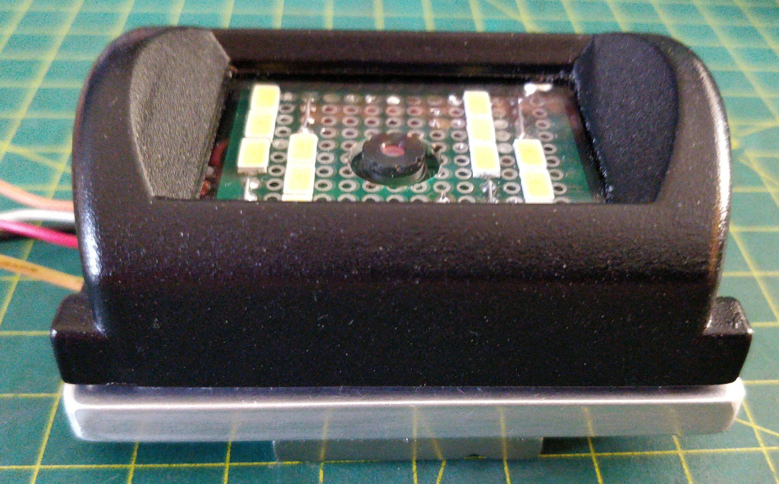
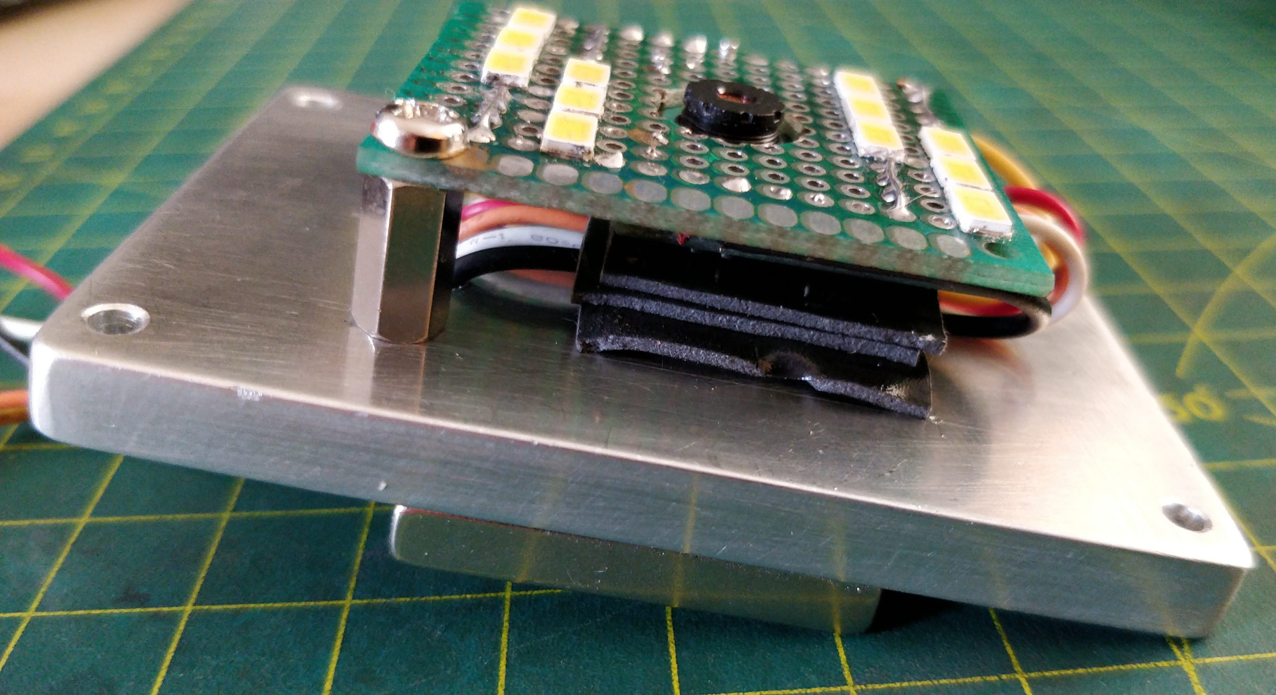
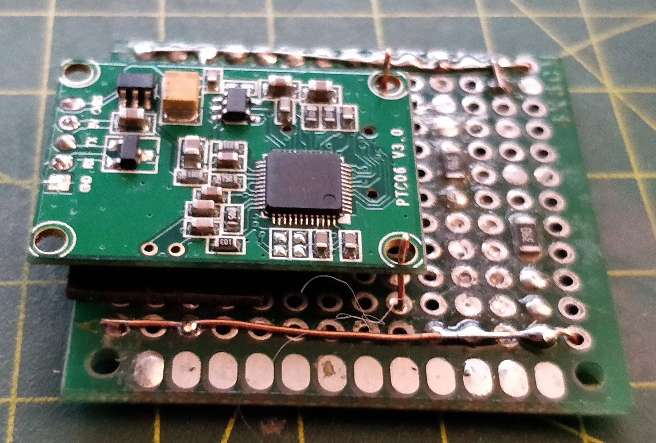
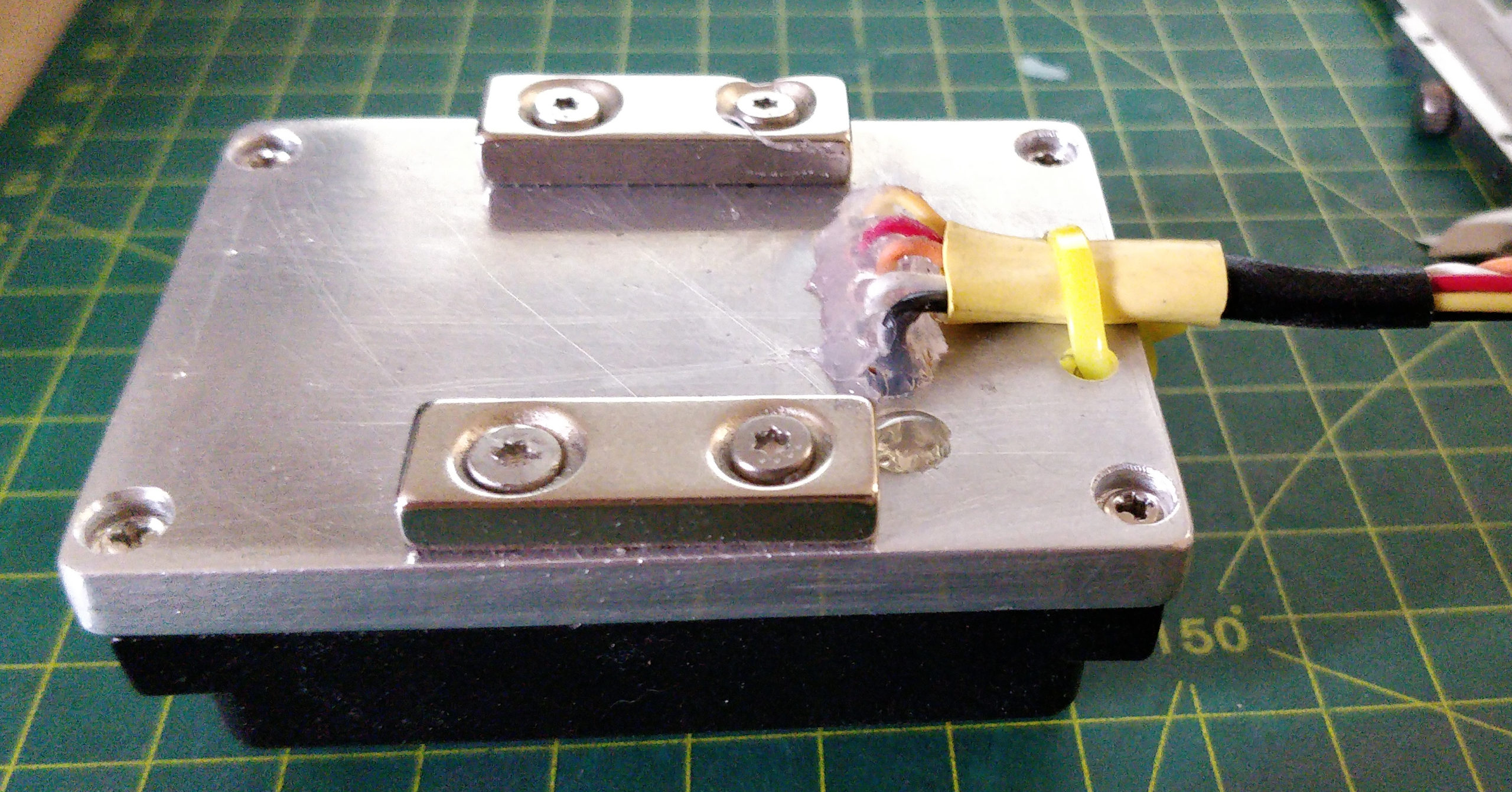
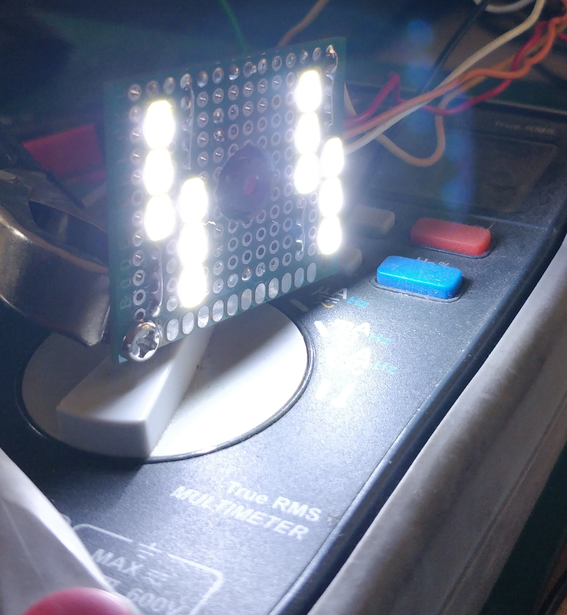
The below are the pictures of the set up I am using this camera with.
It housed in a re-purposed front half of the enclosure from a cheap reversing analogue camera and a custom made aluminium back plate. The LED array is build using LEDs out of cheap LED strip, basically there are 4 parallel strings of 3 LEDs and 39 Ohm resistors. These add up to about ~3W. The whole thing is controlled by two high side MOSFET switches (12V and 5V rails). I didn’t want to use low side switching because it would split grounds and increase pin/wire count.