I recently bought an Opus BT-C100, as unlike my other Lithium Ion chargers, has a discharge test feature. It also fairly quickly estimates internal resistance of the cell, which is a good health indicator.
Unfortunately due to A123 26650 cell being of upside down construction I released the magic smoke out of the Opus BT-C100 by reversing polarity. The smoke escaped through the battery holder slit.
After having battery put in backwards (that can actually supply 100A or so with ease) and smoke escaping, the charger did not have a self check to determine something was wrong and was happily overcharging the batteries. It would attempt to stop charging only to have batteries go above 4.35V. I didn’t want to experiment to see how high it would go (probably around 5V). I suspect the discharge test was also affected as the discharge resistors (2x 1Ohm 3W) got fairly toasty.
So what blew up, one might ask?
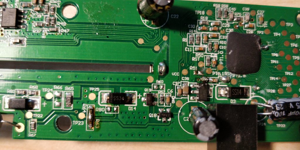
Q19, a P-channel SOT23 MOSFET. Unfortunately it is impossible to say what kind of MOSFET precisely due to generic markings.
Here is the blown MOSFET:
Here is the MOSFET sucked out:
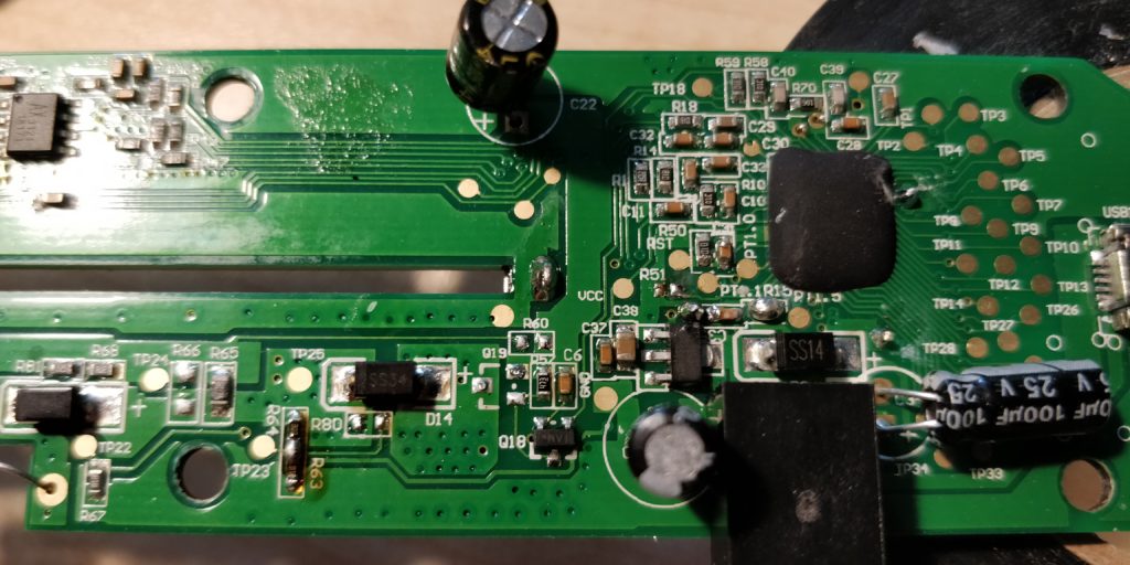
I cleaned the pads off the old solder and used leaded stuff.
New MOSFET:
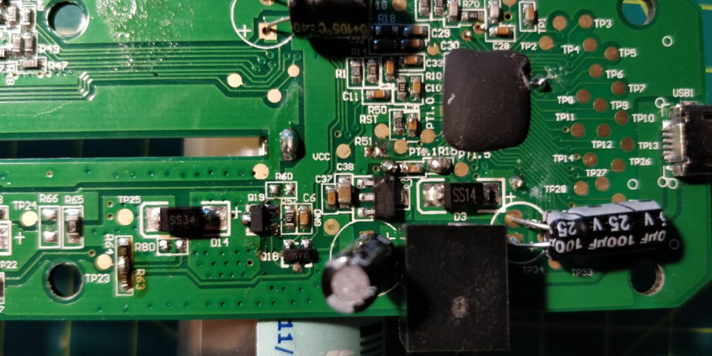
I got some IRLML2244TRPBF from a local supplier, the choice was based on maximum current capability, voltage,price and SOT23 form factor. These are rated around 4A 20V, which should be sufficient for this use as the charger is supplying 2A max.
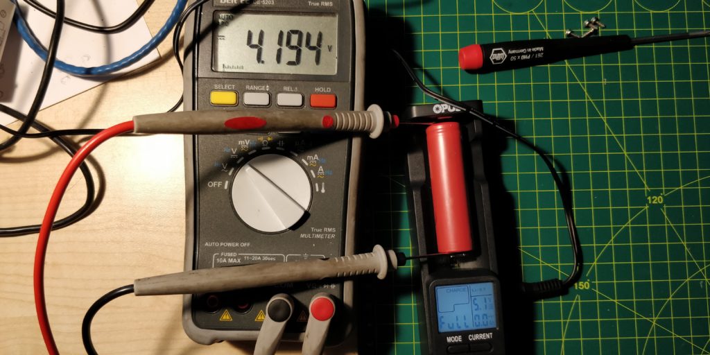
I tested the operation of the charger by monitoring the cell voltage with a multimeter. Indeed the the charger this time actually stopped charging at 4.2V.
The charger supposed to have reverse polarity protection, and reverse engineering portions of the circuit it has diodes that supposed to do so. Why did it fail?
I suspect the reason why it failed is due to inherent reverse diodes of the power bank feature control MOSFETS. The big brother Opus BT-C3100 does not have that feature , and I assume it uses same circuitry. The designers simply didn’t account for the diodes in the power bank side that would reverse through the boost converter coil and blow the charge control MOSFET (Q19) by overloading diode in it.
While I was testing this charger I found that it does not use true CV and CC charging, or even switch-mode approximation, instead it uses ~1s pulses and guestimates the current. So potentially the cell “sees” voltages a lot higher than 4.2V for short period of time ( I measured 4.5V on some small capacity protected cells). I expect this strategy allows them to edge a lot closer to CV region, thus reducing charging time.
This charger seems better on the paper than it is. There would have been a better way to display things. It could have naturally cycle through all parameters every 0.5s of second instead of requiring pressing a button.
I still haven’t figured out what charge test does. The only useful thing for me out of this charger is the discharge test, I am yet to ascertain if the numbers are close to reality.
Mod-ing this charger…
I would beef up the discharge resistors to 5W. Drill some holes in the case where resistors are. As they are the case is already melted (possibly due to being blown previously?). Figure out if it is possible to add another Schottky diode between the battery and 5V power bank circuit.
Either add a switch or diodes so the LED back light is not on when the charger is only powered by the battery.
Hi,
Had the same (user)error, replaced the very same MOSFET, works again!
Thanks a lot for the well documented how-to!
Well written article! I replaced my with the same chip and it working perfectly! Thank you for the research and the write up!
As mentioned in this post, the transistor seems to be labeled 1AMR and is MMBT3904L.
In my opinion this charger is no good until you prevent the reverse polarity issue. Otherwise it is bound to happen again, and if you fail to notice the charger will happily overcharge batteries and either kill the battery or also burn your house down.
Any further tips on how we could fix this design flaw? Preferably while keeping the power-bank function.
Just wanted to add my own case here:
Had a reverse polarity incident and smoke, after which the charger would overcharge my cells.
I ordered new MOSFETs but when I came around to testing the charger before I soldered the new MOSFET in I noticed it had broken down further, it was no longer taking in power from either of the two powers inputs. If I put a cell in the charger would turn on, but if I removed the cell and plugged it into a wall socket it did not turn on. It also would show 0A when charging. I replaced the MOSFET hoping that would fix both the overcharging and the power input, but the power input has not been fixed. I replaced the MOSFET a second time just in case I screwed up the soldering but that made no difference. I don’t know how to find what else could be malfunctioning, I don’t see any other swollen components, but it has to be something related to power in. Sadly without any help I probably have to toss this one out and buy a new charger of a different brand. It saddens me, cause I have an oscilloscope and the time to troubleshoot this but I just lack the experience.