I have decided to switch back from 8mm lens to 3.6mm lens (Mega brand, sold as 3.6mm, f2.3, M12, for 1/3″ sensor).
Disassembly is fairly straight forward.
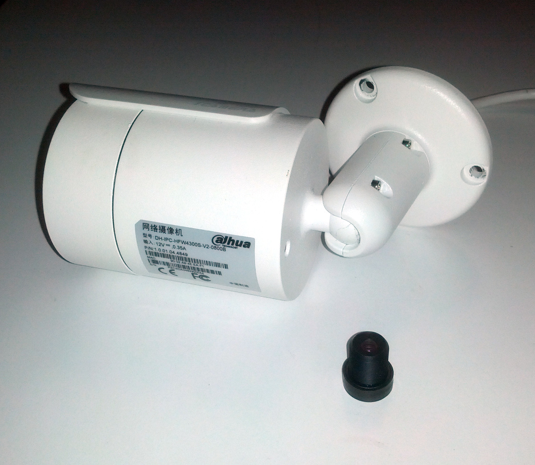
Note: there is no need to remove screw from the back of the camera. It looks like it is covering a breathing hole (the screw does not hold anything).
Unscrew the front half:
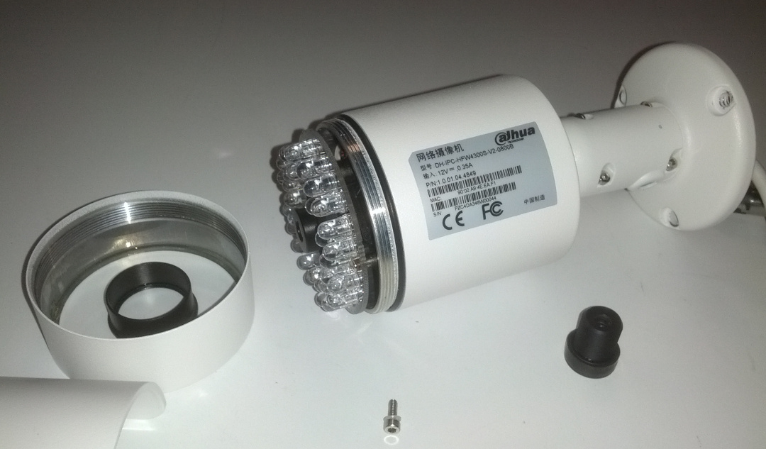
The IR LED PCB is held by couple of screws:
In case of lens change there is no need to disassemble further. But for curiosity I continued.
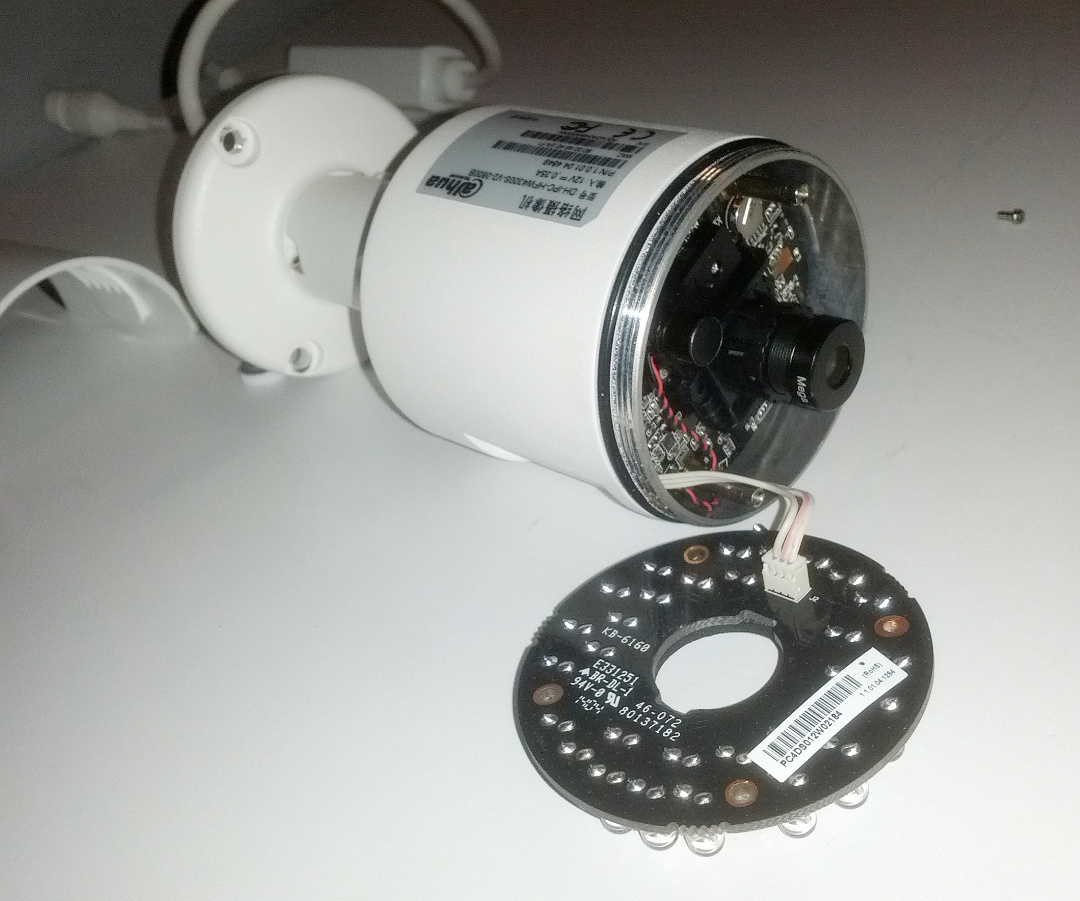
The SoC board is held by another couple of screws and two screw posts that IR LED PCB was screwed into. These posts can be unscrewed by flat screw driver.
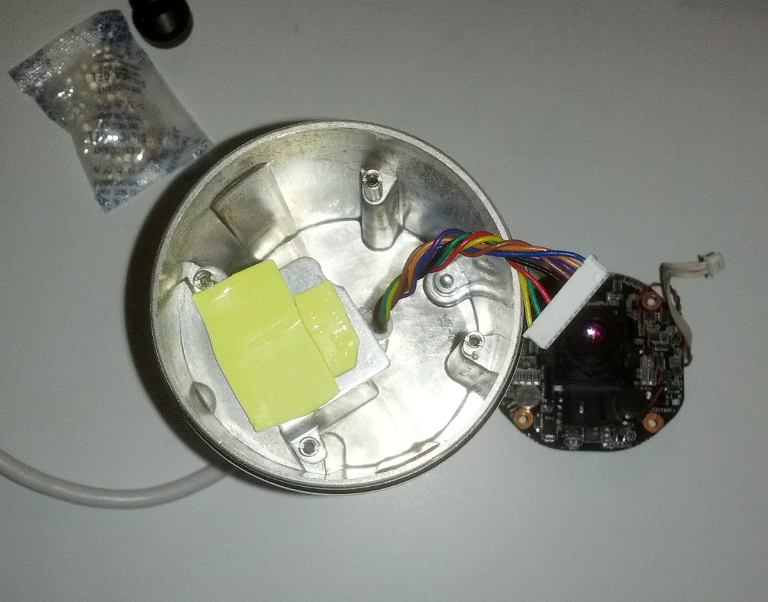
Interestingly enough the camera is mostly empty space, the raised part of the body inside is used as heat sink (covered by yellow heat sink pad). There was a bag of silica gel inside.
The SoC board with lens:
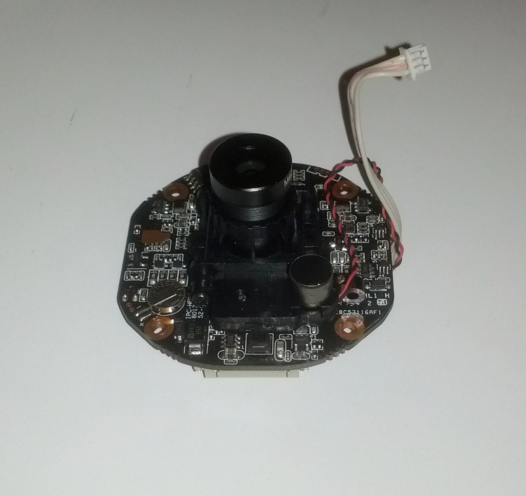
Lens is simply threaded on the sensor body, secured by locking nut. Everything was finger tight. The locking nut is transferred to the new lens and then the whole thing is assembled back, except IR PCB and front cover. Focusing is done on live camera, preferably with a special pattern. The trick is slightly “over” focus, and then tighten the locking nut (while holding the lens).
Back of SoC board:
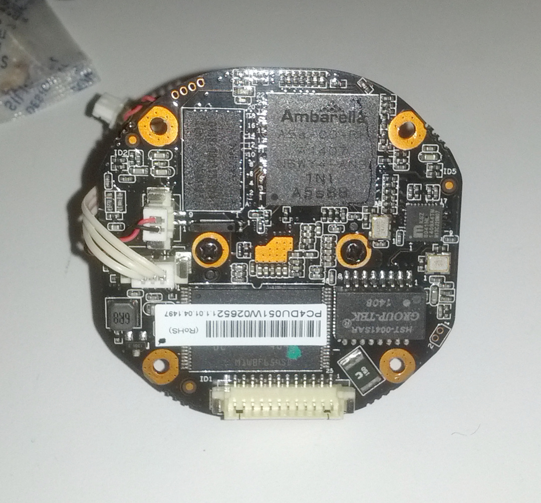
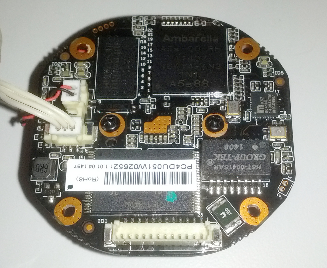
Here what states on the “CPU”:
Ambarella
A5s-CO-RH
A1407
N6WY4-AN3
1N1
A5s88
Here is the front of SoC with lens removed:
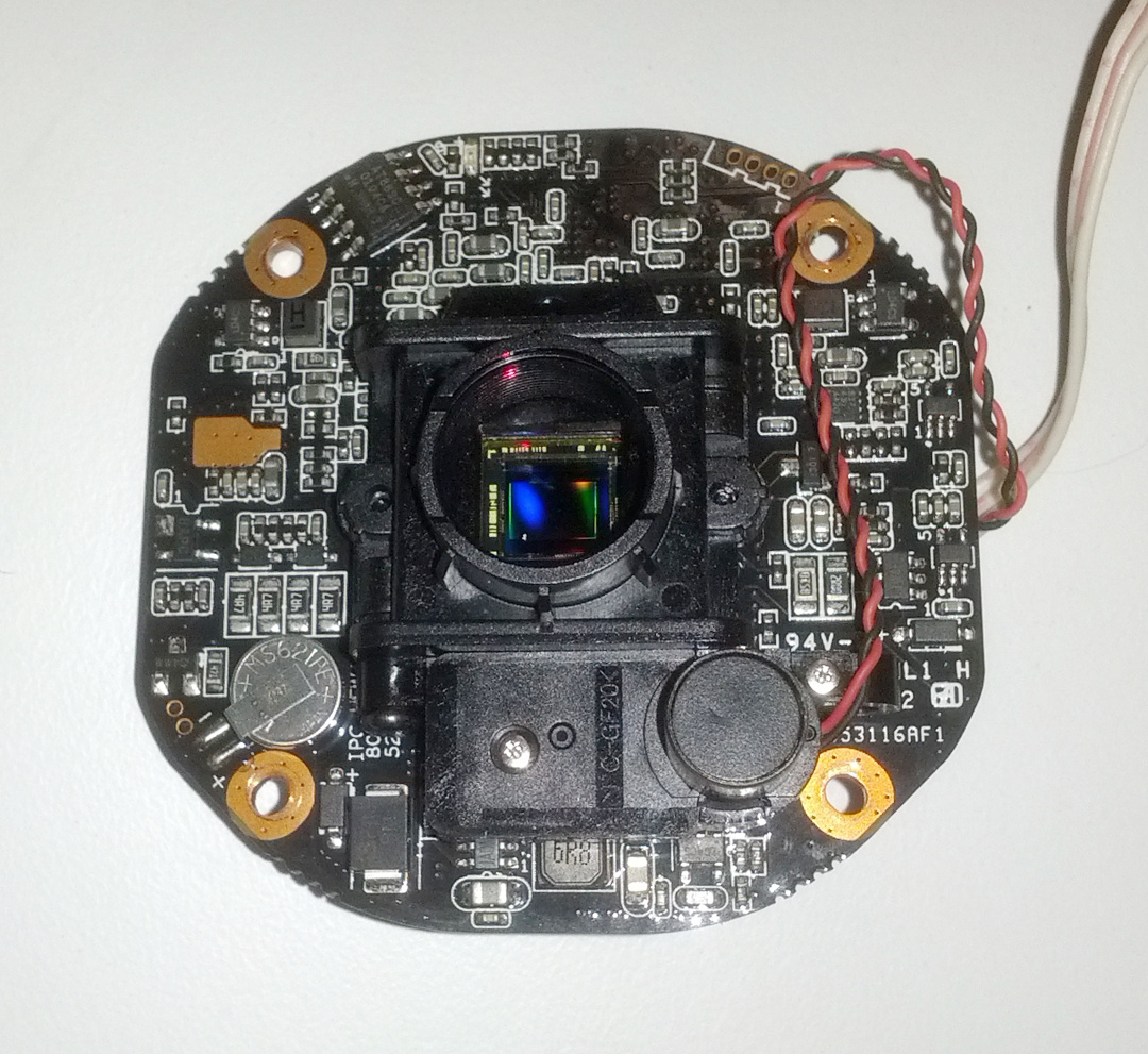
The dust speckle on the sensor was courtesy of Chinese aliexpress seller (probably when they replaced the lens to 8mm).
EDIT: the unpopulated 4 pin header (top right) is for the Serial (RS232) connector, the unpopulated 2 pin header (bottom left, next to battery) is for the reset button.
I used a bit of sticky tape to remove the dust speckle without leaving anything else on the IR filter.
The screws were one time use only (made out of Chinesium) so I replaced them with nice stainless steel screws.
Hi there!
I was fooled by an AliExpess seller and I brought 2 Dahua HFW4300S V2. This V2 version has 2 major ugly parts: the POE adapter is not in the camera body (and i will try to find a way to introduce it in the camera) and the other ugly thing is the firmware update.. I understood that this V2 is made only for China and the firmware is not compatible with the 4300S version. The camera seems to have something that blocks English firmware from running.
So.. Have you any ideas?
Thanks!
Hi Robert, I have the exact same issue with a Dahua IPC-HDBW-4421R-AS camera from AliExpress.
This is what I found about my camera:
1. Credentials depend on the connecting method:
– Dahua’s ConfigTool for Windows> root:vizxv
– telnet> admin:7ujMko0admin
2. The main binary (/usr/bin/sonia) won’t start if your language files are not named in a certain way, depending on Chinese / non-Chinese version of the hardware:
– mv /mnt/custom/English.txt /mnt/custom/SimpChinese.txt
– edit /mnt/custom/i18n and set “DefaultLanguage” : “SimpChinese” and “Languages” : [ “SimpChinese” ]
– do the same steps in /usr/data/Strings
– keep in mind that the above files are on read-only partitions, and you can’t mount them “rw” on the camera itself, because the kernel is compiled without rw support for UBIFS. We should edit the firmware offline and upload to the camera (how?) or maybe U-Boot can do it over serial.
3. You can connect to the UART serial interface of the camera, presumably this would allow some low-level operations on the flash and RAM. In my case, the UART pins are in this order: RX, TX, GND, VCC. They are unpopulated and located next to the MicroSD card on my camera. I don’t have an UART adapter, so I used a Raspberry Pi to connect to the camera. The pins are connected like this (left side – camera pins, right side – RPi pins):
– GND (or simply the metal case of the camera) -> pin 6 (or any other GND pin)
– RX -> pin 8 (TXD)
– TX -> pin 10 (RXD)
Before connecting the cables, make sure no other program is accessing the serial port: ps aux | grep ttyAMA0
To connect, use: “miniterm.py /dev/ttyAMA0 115200” or “screen /dev/ttyAMA0 115200”.
Unfortunately, I can see U-Boot messages on the serial console, but can’t obtain a shell…
I hope this helps you.
Regarding U-Boot and getting shell see here:
http://sergei.nz/ildvr-inc-mh40d06-or-hacking-cheap-chinese-camera/
Specifically you need to change init in similar fashion:
Basically leave bootargs as it is except changing init=... to init=/bin/sh.
Regarding editing firmware the process is similar to process in this post (although Dahua might pack the firmware differently):
http://sergei.nz/ildvr-inc-mh40d06-or-hacking-cheap-chinese-camera-part-2/
Could you please tell me where to buy 3,6 lens for the same dahua?
I got them off Aliexpress.
HI! can you help me, to connect camera. I have 2 piece of cable whith wires of different colours. I need to connect large rectangular plastic box whith cable, in to the board. what does colours i need to combine?
https://drive.google.com/open?id=0B6dJy7nevs8DaW5NOUYyd2o2R1E
It`s a linc whith picture.
So, i Identified colours which conformity to RJ45. It`s white/blue – 1; white/green – 3; blue – 2; green – 6. Others, like violet and brown- it`s a LED on plastic box. Red and black are standart.
But, what a colours from a camera to RJ45?
Hi, I don’t have a spare camera here, so I cannot help you immediately.
I believe you are missing PoE converter box (if you have same version, earlier versions came with PoE circuitry inside of the housing). I also suspect that there will not be a 12V input on the camera, but most likely 5V (which also is being taken care of in PoE box you are missing). Off course I could be wrong here.
The closest spare HFW4300S is about 100km away, and I will only be able to look at it in a week or so…
I am going to take a guess here (check with multimeter against components on the board!):
Red: +VCC
Black: GND
Violet+Brown: matches Violet+Brown on the plug
Green: Green (RJ45, TX-)
Yellow: White/Green (RJ45, TX+)
Orange: Orange (RJ45, RX-)
Blue: White/Orange (RJ45, RX+)
Possible above is very wrong!